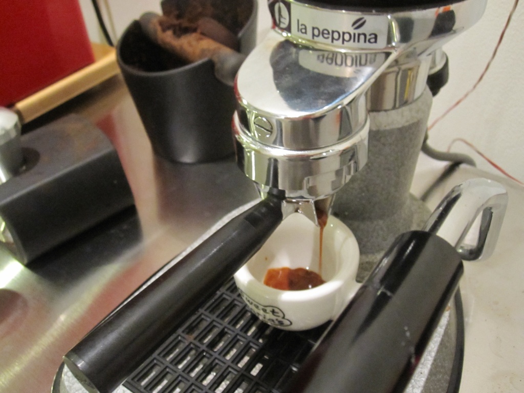
A few months ago I bought a La Peppina. It is a quirky little machine -- a vintage Italian-made lever espresso maker for home use. It is capable of very good results, but requires a little attention. The main issue is that, with an 1100 Watt heating element and a small-ish kettle, it will acheive a full rolling boil in about 5 minutes. Normally, one would allow the water to boil, flush a few pulls to heat the group, then switch off the heating element and wait for the water to cool to optimum brew temperature before pulling the shot. This process is certainly workable, but it can be somewhat difficult to reliably hit the desired brew temperature. Adding PID control to the machine allows one to walk up to a temperature-stable machine, perform a quick flush to heat the group, then pull a shot with no waiting. It also allows the machine to be left unattended for reasonable periods of time (a recipe for disaster with the stock machine).
Instead of somehow building the PID controller into the La Peppina, I decided to build a stand alone PID control box. This way I can also control other processes in the future should the need arise (e.g. a kettle for french press coffee, a coffee roaster, perhaps even a steam table for sous vide cooking). In fact, just about any resistive device that plugs into a wall outlet can work with this controller.
The controller is based around a PID controller, SSR, and RTD temperature sensor, all of which were purchased from Auber Instruments.
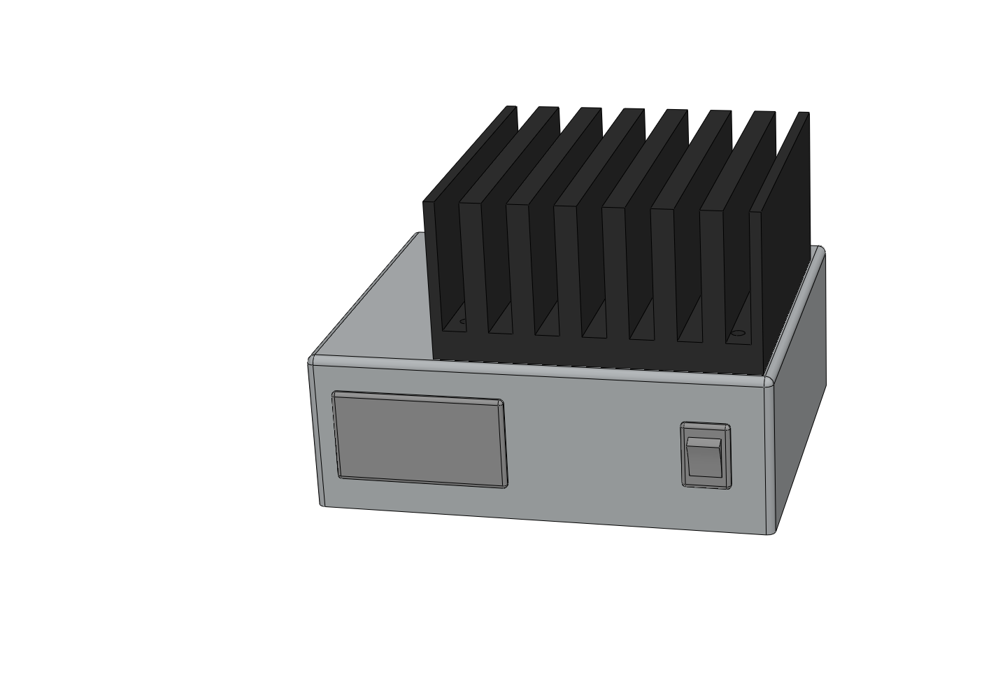
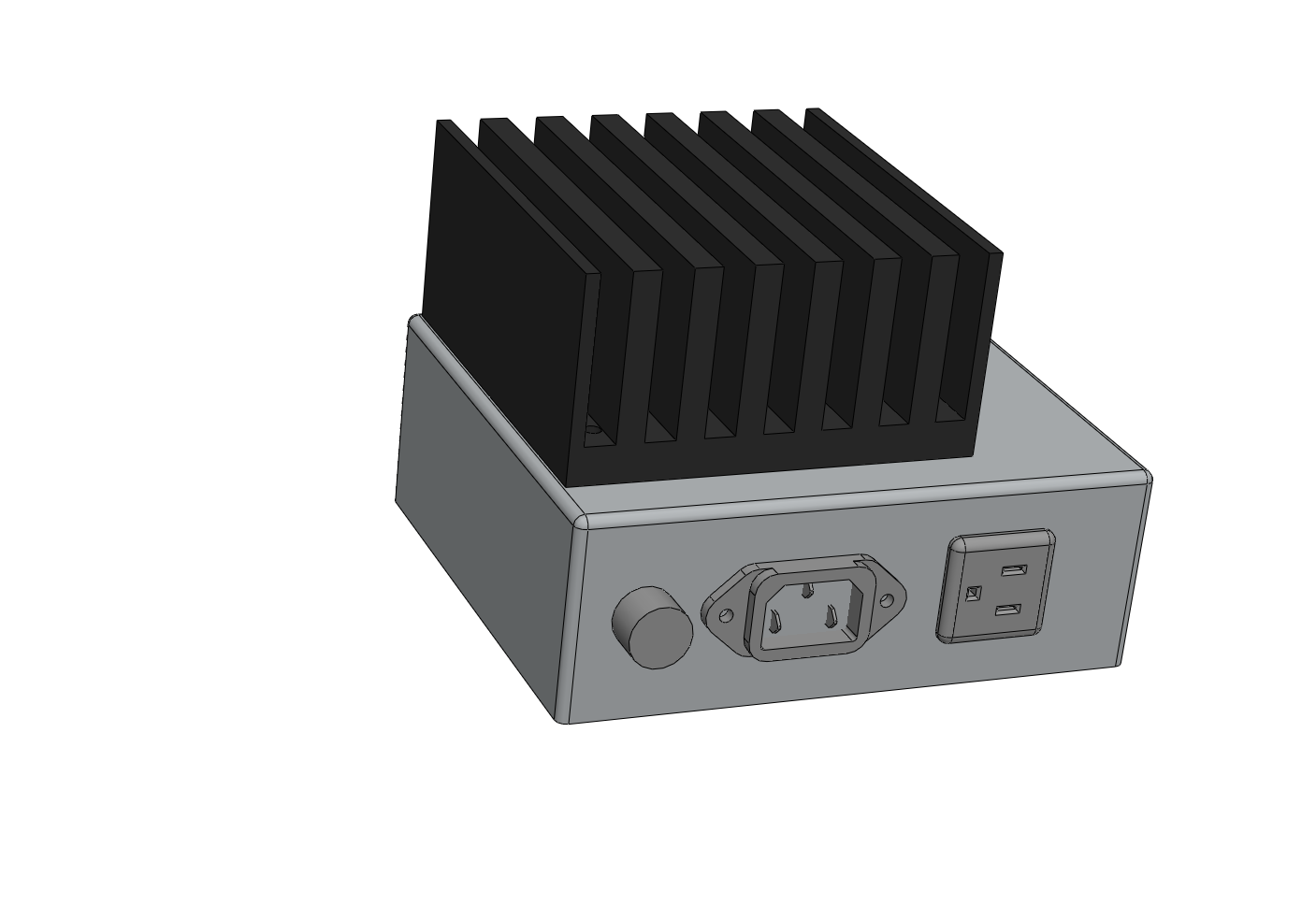
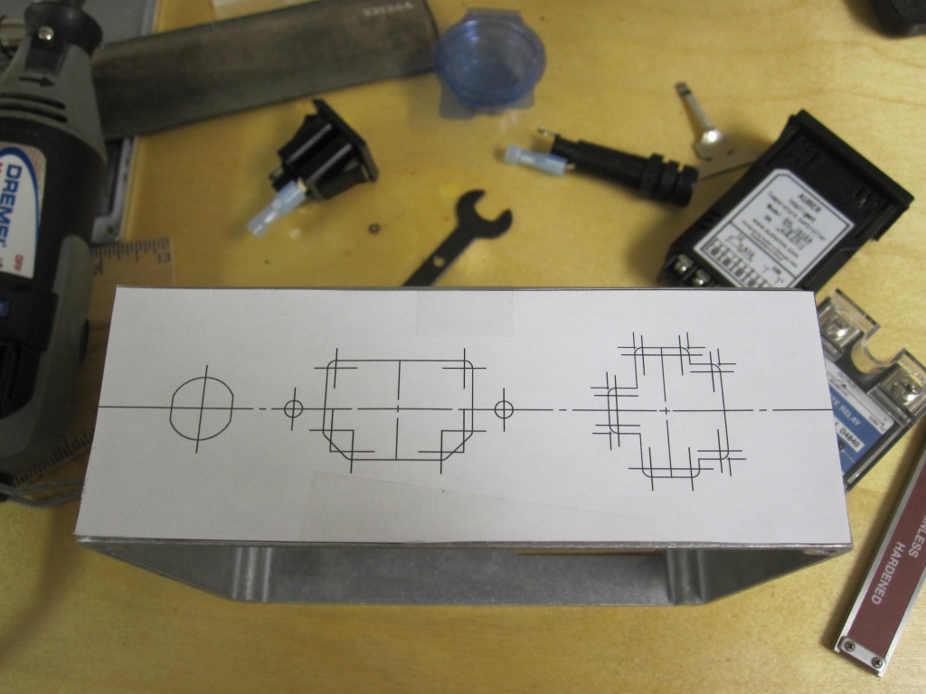
Below is a 2D rendering of the PID controller. This model was constructed to ensure all the parts would fit in the box I selected. I only bothered to model the major features, which is way it's so plain looking.
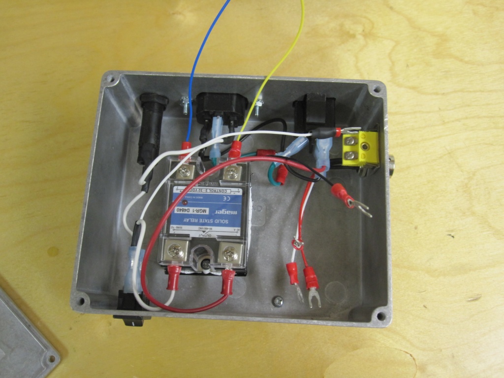
This is a fairly simple device to construct. There are two main tasks: making the panel cutouts and wiring everything up. The panel cutouts are explained below. For the wiring, I chose to use quickconnects and spades. The parts were chosen to have 0.187" quickconnects; however, there are two different thicknesses: 0.020" and 0.031". For the spades, #6 and #8 spades were needed. I used 18 gauge wire for the high-current connections, 16 gauge for grounds, and 22 gauge for signal connections, primarily because this is the wire I had on hand.
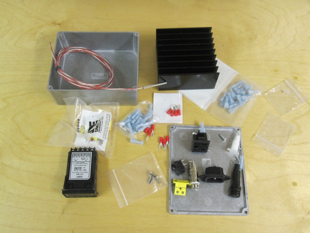
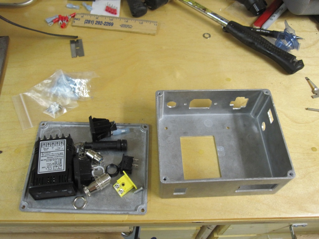
All the parts laid out
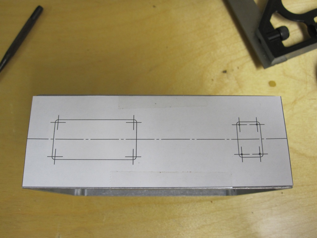
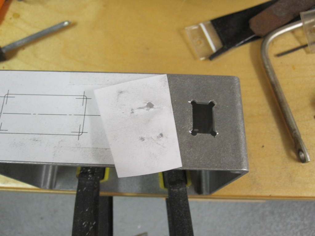
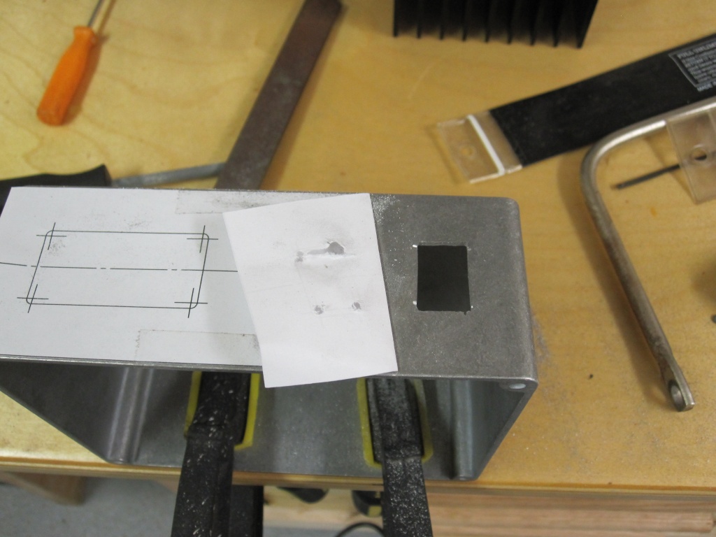
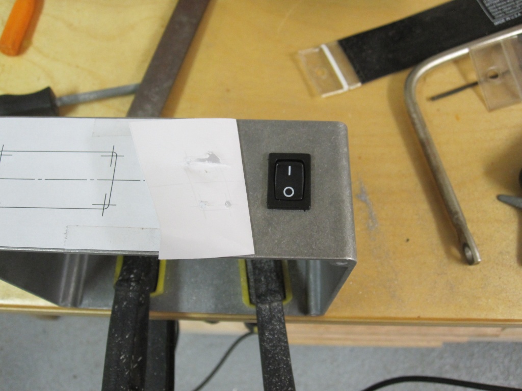
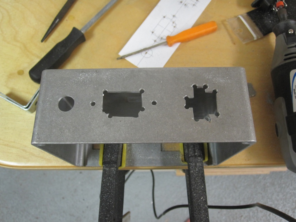
Making the switch hole. First I fitted the paper template and marked the holes with a punch. Then I drilled pilots with a 1/16" drill bit and drilled out the holes with a 1/8" bit. I cut out the material between the holes with a cutoff wheel in my Dremel tool, then finalized the shape with a file.
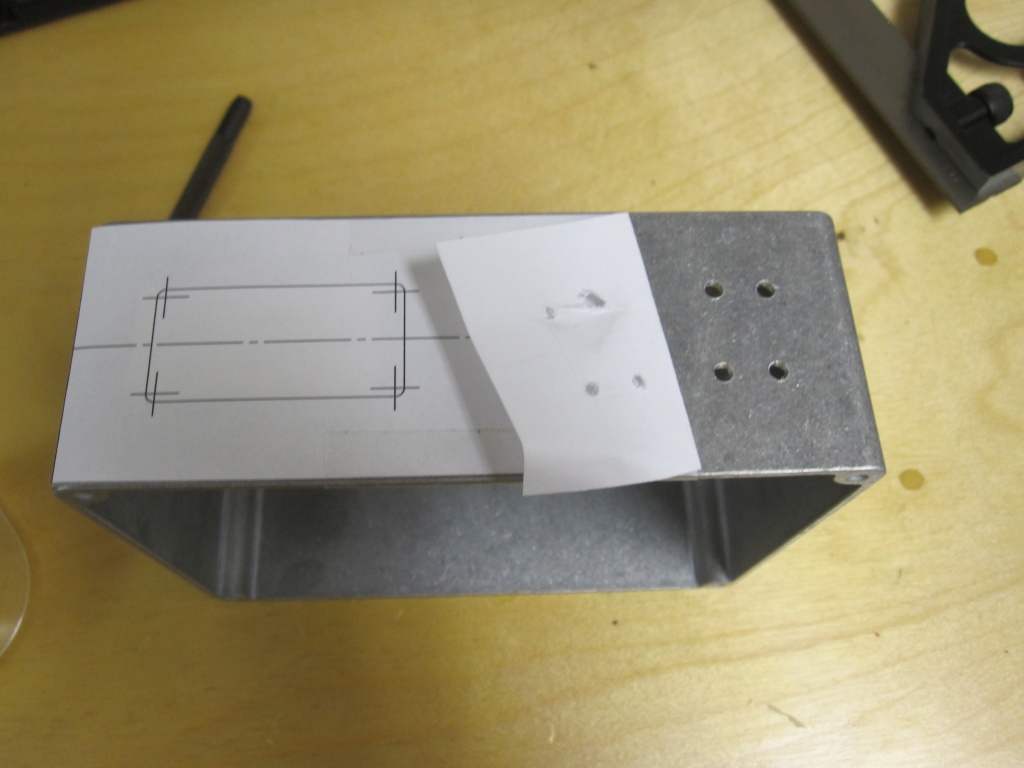
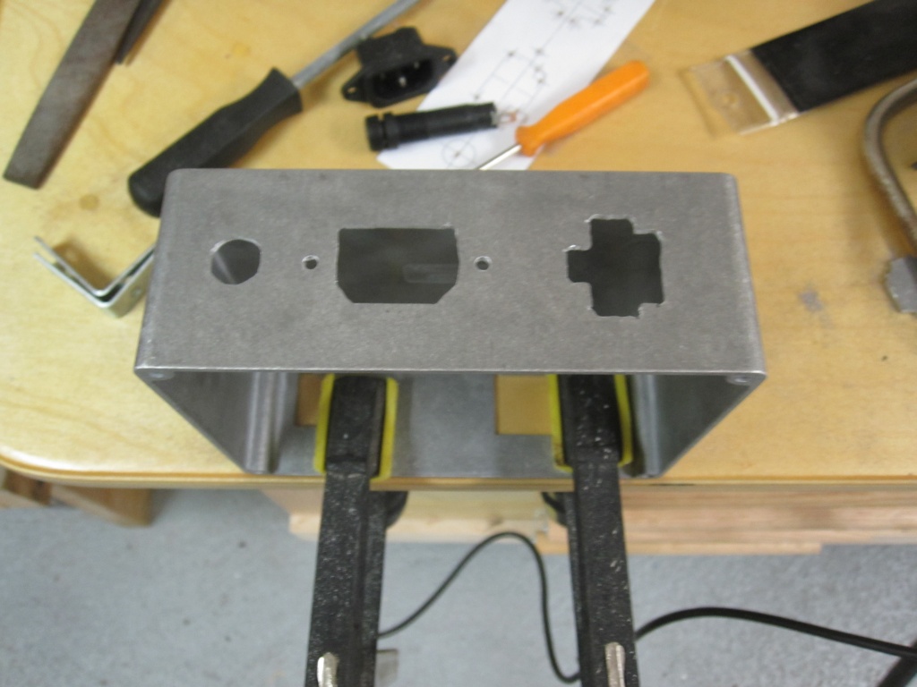
Same process for the back panel cutouts.


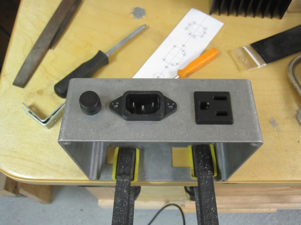
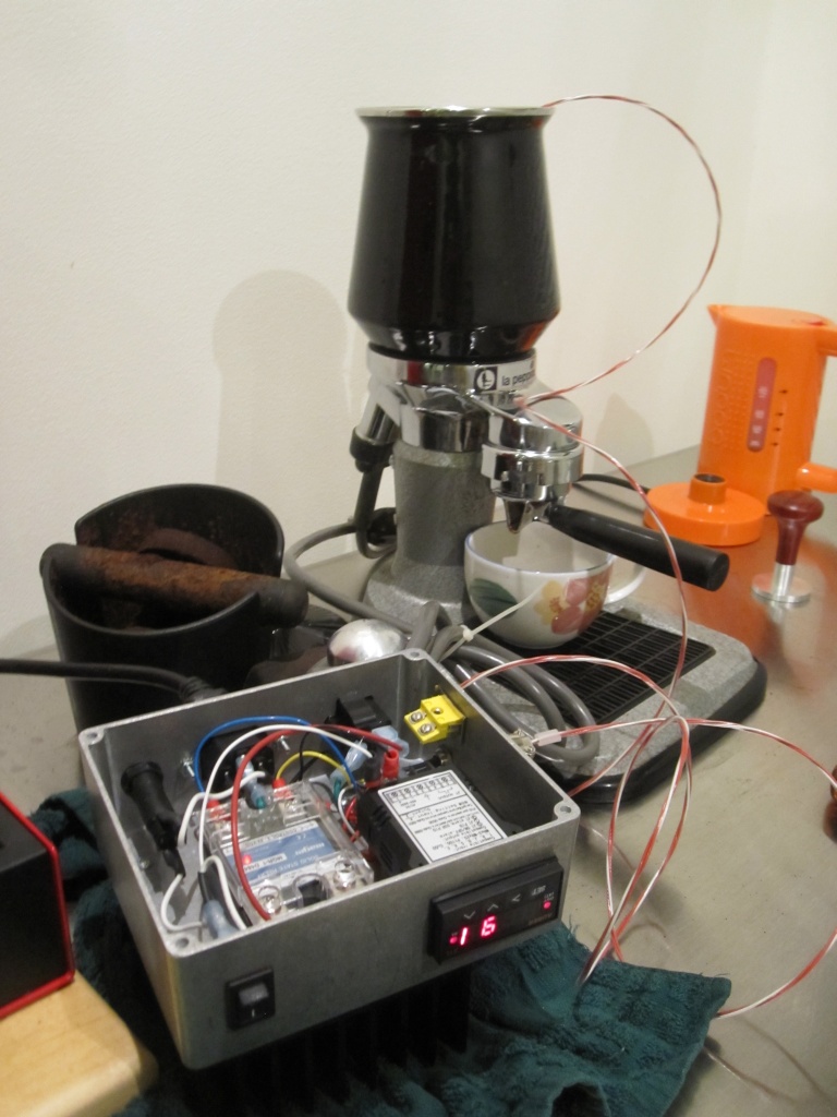
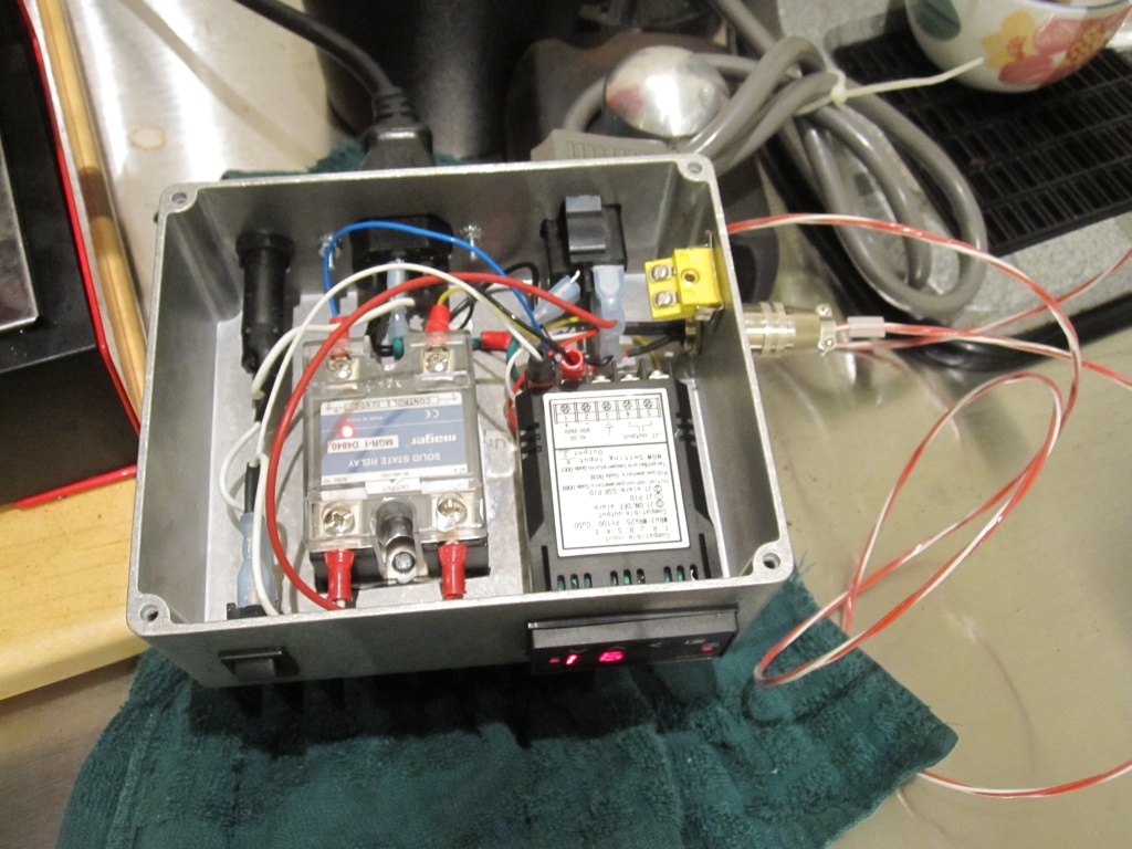
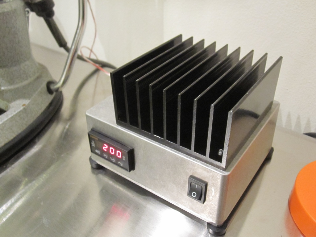
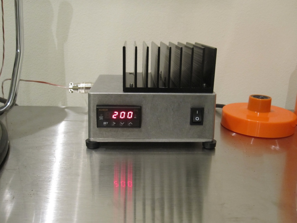
Box with all cutouts finished, partially wired box ready for PID installation, and nearly complete box under test.
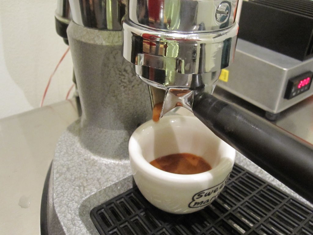
The finished PID control box hooked up to my espresso machine. Setting up the PID controller was a simple matter of changing the input type to RTD, and running the auto-tune routine to set the PID parameters.
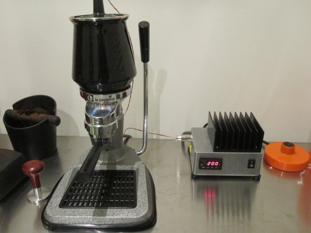
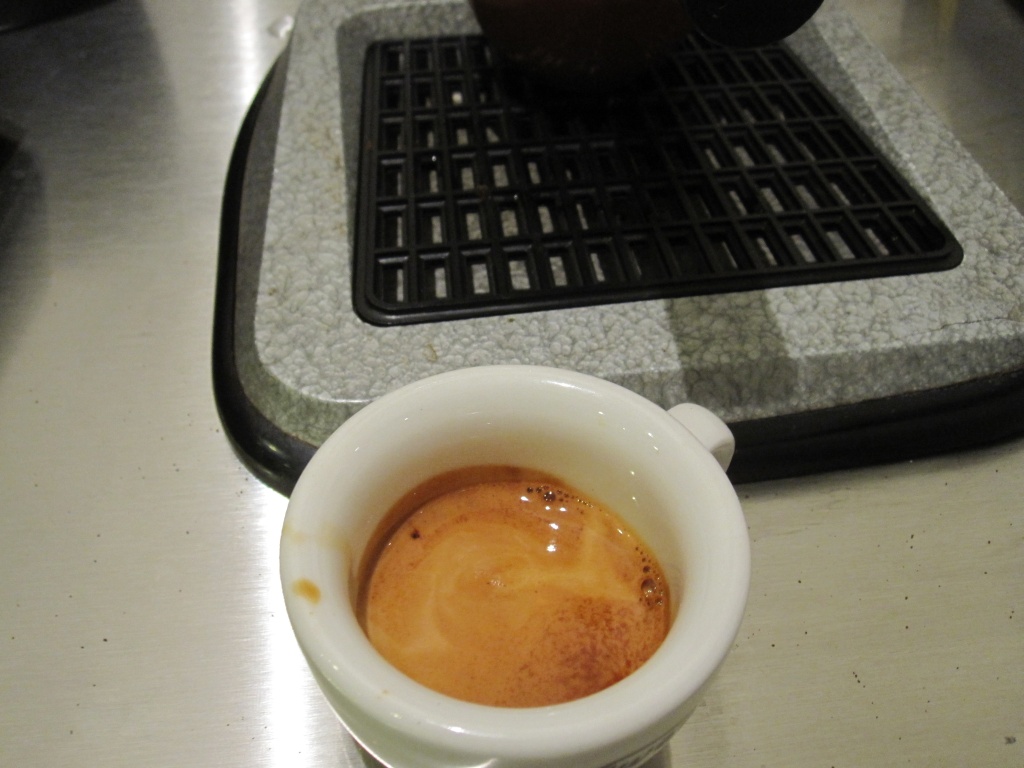
The first shot pulled with PID temperature control. Not bad!