2:1 mixer, version 2
Overview
My original mixer had a couple of shortcomings -- non unity gain, the need for matched source impedances, and unnecessary (for my purposes) level controls. So I decided to build a new, better mixer.
Design
Schematic
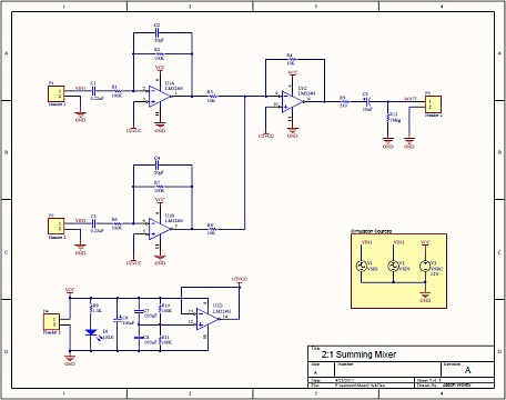
This is a classic mixer circuit with inverting input stages and an inverting summing stage.
-
As drawn, the circuit has unity gain and an input impedance of about 100k Ohms. Setting the input impedance is a balancing act, since increasing the values of R1/R2 and R6/R7 cause increased Johnson (thermal) noise. I felt that 100k was a good balance between noise and compatibility with a number of inputs.
-
The low frequency response is set by C1/C3, which forms a first-order high-pass filter with R1/R6. The indicated values result in a -3dB point of about 8Hz.
-
The high-frequency response is determined by C2/C4, which set the low-pass -3dB point to about 32kHz.
-
U1C is the summing stage, and R3, R8, and R4, set it for unity gain per input channel. Since both the input and summing stages are inverting, the overall result is non-inverting.
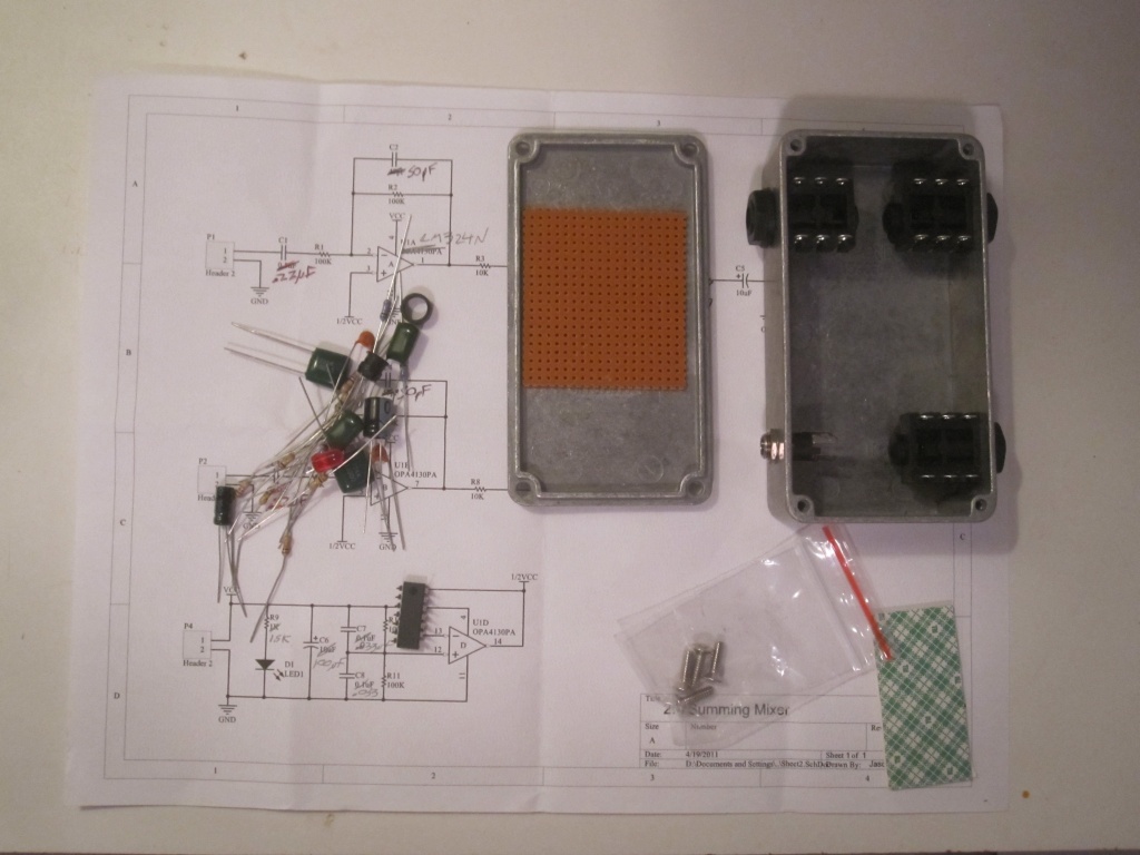
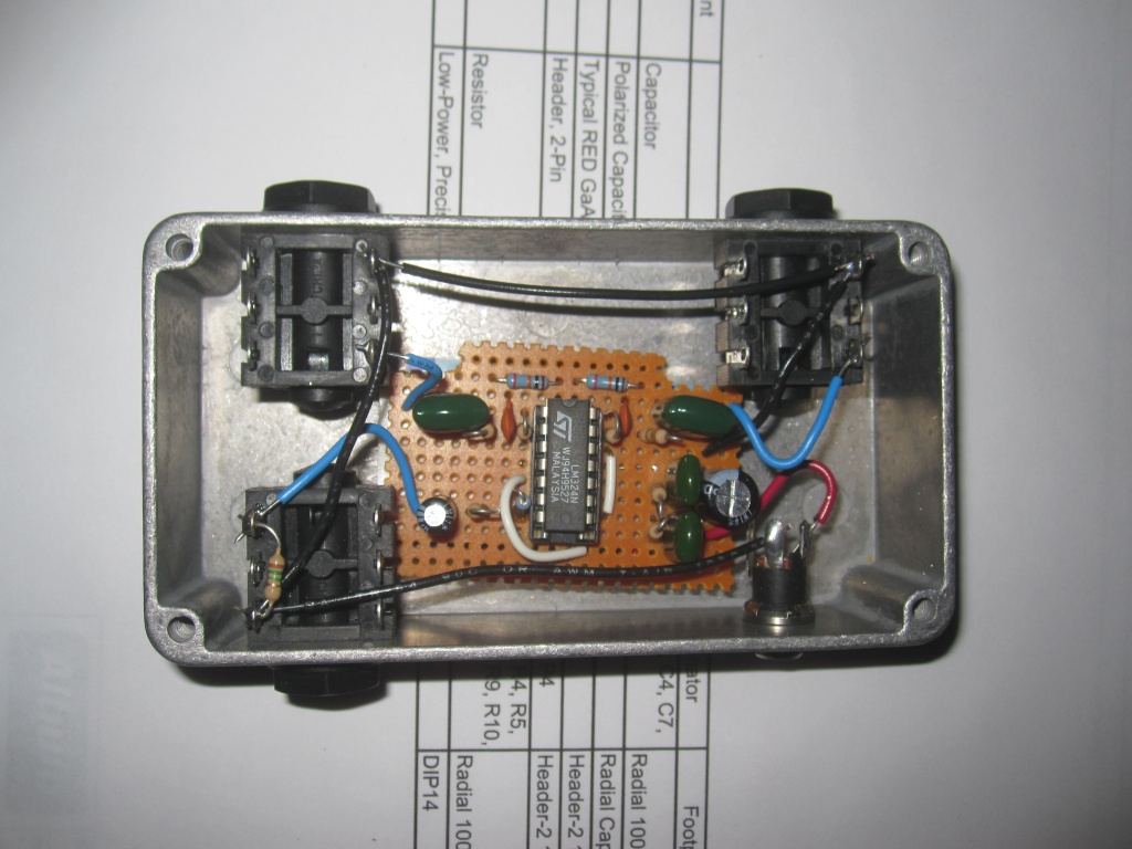
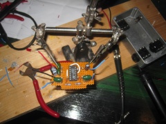
Building it
From left: Case drilled with phono and DC jacks mounted, circuit built on perfboard, completed mixer.
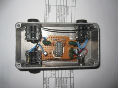
Note that I left out the LED (and R9) because I didn't feel it was necessary.
Home
e-mail: jason@jasonwolley.com